Help Matching
The objective of the MATCHING analysis is to obtain the best possible combination of machine, mold and part.
MATCHING Line

At the top we have the MATCHING line which summarizes the steps that we must complete in order to complete our analysis. Once the single step is completed we can go back and forth by clicking on the icons of the MATCHING line. To confirm and validate the single step, you must instead click on the forward icon ‘NEXT’ at the bottom.
Going forward and backward on the MATCHING line we can correct and vary the values entered in order to vary the results and obtain the best MACHING between machine-mold-part possible. In this way we will see the graph and values produced in the report change in real time, thus you can check the quality of the configuration analyzed. It will be possibile to save all the configurations / variants you want by calmly value how to proceed in the Filling.
It will also be possible to create variants of a project using the “save a copy” function available in the first phase “PRELIMINARY PROJECT DATA”. This function duplicates a Matching project already carried out.
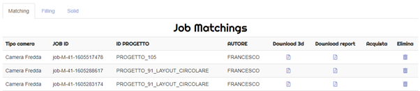
The Job Matching that will be purchased or sent to Filling for the analisys will no longer be available in the Matching area but you can consult them in your personal area “My Job”

By clicking on the (+) of the search section, you can consult useful tips that will help you in filling in each field
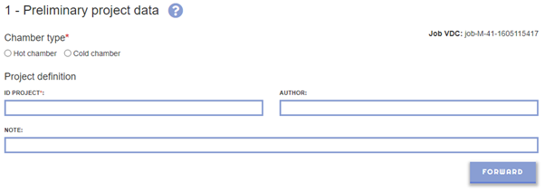
In this section we will choose the molding technology (hot vs cold chamber) and insert all the data that concern with the ‘management’ of the analysis.
1.1 Upload a project. It is possible to recall a previously saved Matching project.
The “Load a Project” menu will only appear if there are previously saved projects

If you want to develop different configurations from an existing JOB MATCHING, use the SAVE A COPY function.

1.2 Hot chamber vs cold chamber. The top choice. We define if our analysis is for hot or cold chamber. Needless to say, this field is mandatory.
1.3 Project ID. We insert our reference to the current project. This is an alphanumeric field that we can use by referring to our order number, project, customer, rather than a specific version of the project. In short, anything that allows us to identify after the time of the work done. Remember that this will be the field that will appear on the cloud to identify the job.
(*) It is an indispensable field for proceeding with the job processing. Remember: all fields with a red asterisk are essential to go on. They must be compiled. Those fields without an asterisk, on the other hand, are not mandatory and can be skipped in the compilation.
1.4-Author. If your company has a single account and you have more people accessing it by working on the VirtualDieCasting portal, it can be useful to specify the author of the single job in order to better identify the job, to be able to do some order between who does what and to have a more effective search key later when you have all your jobs. This is not a mandatory field.
1.5-Note. It is a free alphanumeric field. Here you can insert everything your imagination leads you to do in order to better frame and remember in the future the specifics of the job you are creating. It is not a mandatory field.
2.1 Alloy grade. Select the alloy grade you want to use for this casting from the drop-down menu. If the alloy you want is not present or if you have doubts about the choice of the alloy grade, do not hesitate to contact us. A VirtualDieCasting expert will answer you shortly advising you for the best. It is a mandatory field.
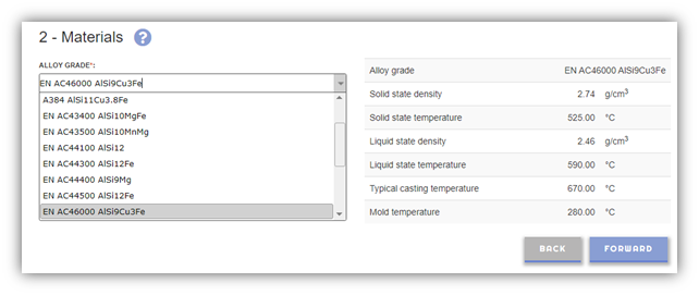
2.2 Die material. Select the type of material from which the mold is made from the drop-down menu. If the material you want is not present or if you have doubts about the choice of the type of material, do not hesitate to contact us. A VirtualDieCasting expert will answer you shortly advising you for the best. It is a mandatory field.
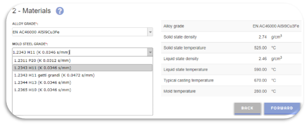
Process data for the choice will appear on the right
(*) mandatory field to fill in to continue
MOLDING MACHINE (HC)
For hot chamber
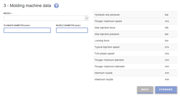
3.1 HC Machine model. Select from the drop-down menu the molding machine you want to use for this analysis among those available. If your machine is not available, you can use a similar tonnage. If the machine you want is not present or if you have any doubts about the choice of molding machine, do not hesitate to contact us. A VirtualDieCasting expert will answer you shortly advising you for the best. It is a mandatory field.
PS: We can characterize your molding machine starting from the injection nomogram and the machine data sheet.
3.2 HC Plunger diameter. Enter the value of the plunger diameter that is available for your molding machine. This value must however be between the minimum and maximum plunger diameter that can be mounted on the molding machine as indicated on the right. It is a mandatory field.
3.3 HC Nozzle diameter. Enter the value of the nozzle diameter that is available for your molding machine. This value must however be between the minimum and maximum nozzle diameter that can be mounted on the molding machine as indicated on the right. It is a mandatory field.
MOLDING MACHINE (CC)
For cold chamber
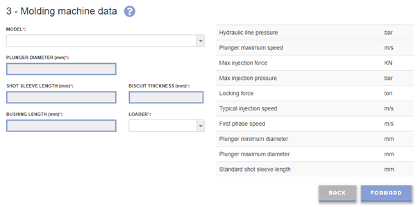
3.1 CC Machine model. Select from the drop-down menu the molding machine you want to use for this analysis among those available. If your machine is not available, you can use a similar tonnage. If the machine you want is not present or if you have any doubts about the choice of molding machine, do not hesitate to contact us. A VirtualDieCasting expert will answer you shortly advising you for the best. It is a mandatory field.
PS: We can characterize your molding machine starting from the injection nomogram and the machine data sheet.
3.2 CC Plunger diameter. Enter the value of the plunger diameter that is available for your molding machine. This value must however be between the minimum and maximum plunger diameter that can be mounted on the molding machine as indicated on the right. It is a mandatory field.
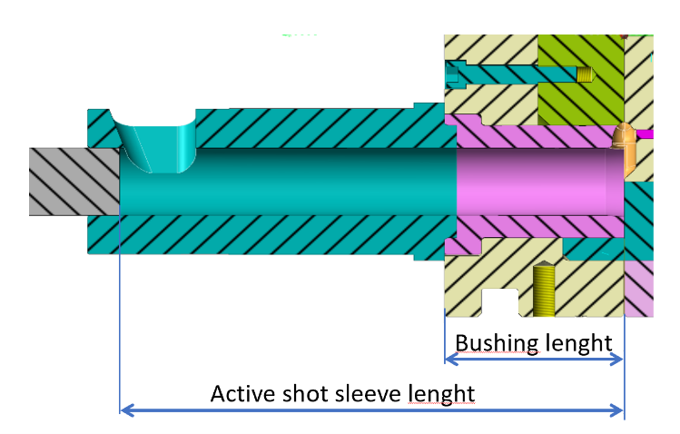
3.3 CC Shot sleeve lenght. Enter the value of the active length of the shot sleeve. It is a pre-filled field based on the selected press model but it is possible to change it. As shown in the picture below. It is a mandatory field.

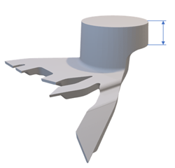
3.4 CC Biscuit thickness. Enter the thickness of the biscuit you want to keep. The thickness of the biscuit is generally less than one third of the plunger diameter. It is a mandatory field.
3.5 CC Bushing lenght. Based on the length of the standard container (shown on the right for the machine selected), the length of the bush is calculated by the software. Use this length value as a check.
3.6 CC Loader. Enter the type of loader used between the Cartesian and the dosing furnace. This field is used to calculate the alloy’s thermal drop. It is a mandatory field.
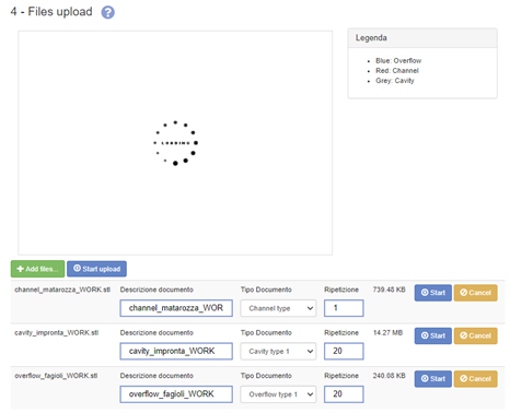
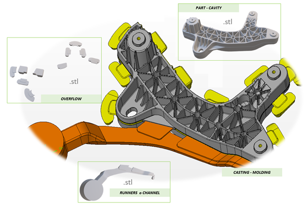
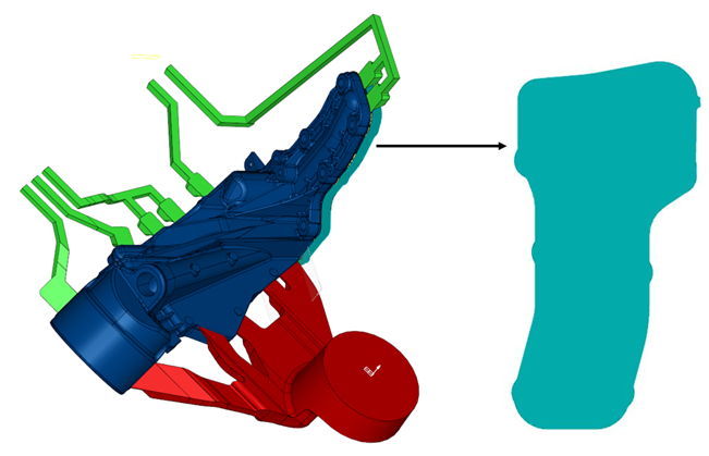
In this section you have the possibility to individually load the parts of the molding: cavity, overflow and channel ( Biscuit + Gate ). The loading will allow the automatic extrapolation of some technical data such as weight, volume, front surface. At each loading it will be necessary to specify the part of the casting and the number of repetitions by type:

If you have no file to upload, you can go to the next ‘CASTING DATA’ step and enter the information manually.
EN
- The maximum file size for uploads is 200 MB
- In this session upload only STL files (.stl)
- You can drag & drop files from your desktop on this webpage (see Browser support).
- Every data or file uploaded by the user is treated by TF sas as CONFIDENTIAL INFORMATION according to the secrecy agreement (NDA) validated during registration of virtualdiecasting.com
EXAMPLE 1
EXAMPLE 1
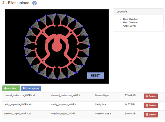
Number repetition:
- Cavity repetition: we indicate how many times the type of cavity is repeated
- Overflow repetition: we indicate how many cavities the type of overflow refers to. It is always equal to the repetition of the associated cavity ( Example 2)
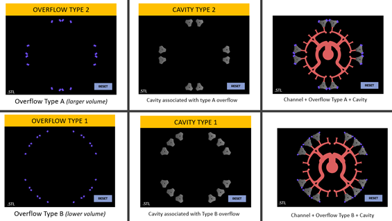
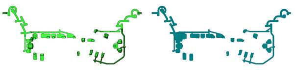
Example 2 which the same cavities are loaded as a different “Type” as they have a different overflow configuration:
EXAMPLE 2
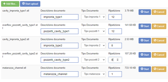
EXAMPLE 2
In this section we insert all the geometric data relating to our casting.
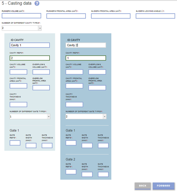
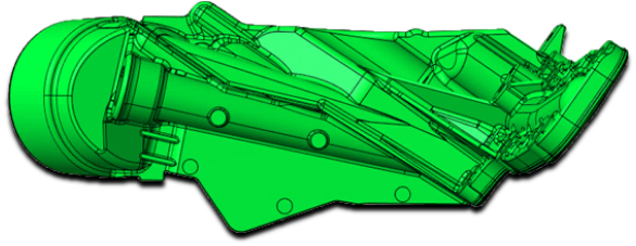
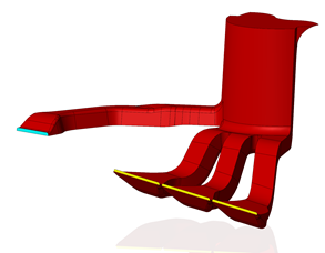
What do we call the various parts of the casting? To enter the correct data it is useful to introduce a shared terminology. We refer to the following image.
5.1 Runners volume. Enter the volume of the runners in cm3. If we have a 3D geometry available we can use any 3D CAD to make this measurement (see FAQ for advice). If we proceeded to load the geometry in .STP format in the previous step, the data will be calculated automatically. It is a mandatory field.
5.2 Runners frontal area. Enter the runner frontal area in cm2 projected orthogonally to the opening direction of the mold. If we have a 3D geometry available we can use any 3D CAD to make this measurement (see FAQ for advice). If we proceeded to load the geometry in .STP format in the previous step, the data will be calculated automatically. It is a mandatory field. See the following image.
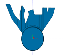
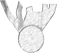
5.3 Sliders frontal area. Enter the slider area projected orthogonally to the slider opening direction. This area must be expressed in cm2. If we have a 3D geometry available we can use any 3D CAD to make this measurement (see FAQ for advice). If we do not have slider it must be set to zero. It is a mandatory field. See the following image.
Projected area orthogonal to the direction of movement of the slider
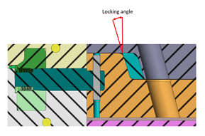
5.4 Slider locking angle. Enter the locking angle of the sliders. If we have multiple sliders with different locking angles we indicate the largest. This value requires knowledge of mold mechanics. If we do not have sliders, it must be set to zero. It is a mandatory field.
See the following image.
5.5 Number of different cavity types. By this number we mean the number of different types of cavity in the mold, not the total number of cavity. For example: if our mold has a two same cavity the number of different cavity is 1. If we have a family mold with 4 cavity type A and 2 cavity type B, the number of different cavity is 2. We can specify up to 5 different types of cavity in the mold. It is a mandatory field.
For each type of cavity (1,2,3 …) we must indicate the following fields.
5.6 Identify cavity By default the cavities are identified as cavity 1, cavity 2, etc. It is possible to change the name by entering the identifier you prefer. It is recommended not to use longer field descriptions. It is a mandatory field.
5.7 Number of cavity repetitions. Enter how many times the cavity considered is present. In the mold we must have at least 1 cavity. It is a mandatory field.
5.8 Cavity volume. Enter the volume of the single cavity in cm3. If we have a 3D geometry available we can use any 3D CAD to make this measurement (see FAQ for advice). If we proceeded to load the geometry in .STP format in the previous step, the data will be calculated automatically. It is a mandatory field.
5.9 Total volume of cavity overflows. Enter the volume of all the overflow connected to the considered cavity in cm3. If we have a 3D geometry available we can use any 3D CAD to make this measurement (see FAQ for advice). If we proceeded to load the geometry in .STP format in the previous step, the data will be calculated automatically. It is a mandatory field.
5.10 Frontal cavity area. Enter the area of the cavity in cm2 projected orthogonally to the opening direction of the mold. If we have a 3D geometry available we can use any 3D CAD to make this measurement (see FAQ for advice). If we proceeded to load the geometry in .STP format in the previous step, the data will be calculated automatically. It is a mandatory field. See the following image.

Frontal cavity area
5.11 Frontal overflow cavity area.
Enter the area of all the overflow connected to the considered cavity in cm2 projected orthogonally to the opening direction of the mold. If we have a 3D geometry available we can use any 3D CAD to make this measurement (see FAQ for advice). If we proceeded to load the geometry in .STP format in the previous step, the data will be calculated automatically. It is a mandatory field. See the following image.
5.12 General cavity thickness. Enter the average or predominant thickness of the considered cavity. We know it can be a difficult value to indicate. However, it is a important value in the calculation. It is a predominant thickness, not the minimum but limited to some areas, nor the maximum if always limited to specific areas (see FAQ for advice). It is a mandatory field.
5.13 Nr different type of gate. Enter how many different gate types we have for the considered cavity. This is not the total number of gates but only the different types of gates. It is a mandatory field.
In the following example we have 4 gates, three of type A and 1 of type B. For type A the nr. is 3, for type B the nr. is 1.
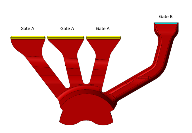
For each type of gate for the considered cavity (gate 1,2,3 …) we must indicate the following fields.
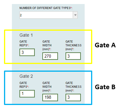
5.14 Gate repetitions. Enter how many times the gate specified is present for the considered cavity. It is a mandatory field.
- Each cavity must have at least 1 gate
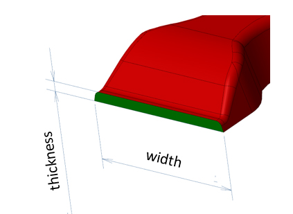
5.15 Gate width. Enter the width of the gate considered in mm. If we have a 3D geometry available we can use any 3D CAD to make this measurement (see FAQ for advice). It is a mandatory field.
5.16 Gate thickness. Enter the thickness of the gate considered in mm. If we have a 3D geometry available we can use any 3D CAD to make this measurement (see FAQ for advice). It is a mandatory field.
In this tab we indicate the technological parameters of the casting process. It is a bit as if we were on side of the molding machine and we could adjust the machine parameters to find the best configuration.
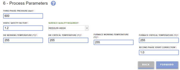
6.1 Intensified pressure. Enter the intensified pressure that we intend to use in bar. This value directly affects the dynamic seal of the mold lock and the porosity expected on the casting. It is a mandatory value.
6.2 Static safety factor. It is a coefficient that allows you to introduce a safety factor in the calculation of the closing force of the molding machine. It is a mandatory value.
6.3 Casting quality. It is the main discriminant for the casting. We have to choose between 5 levels:
- High
- Medium-High
- Medium
- Medium-Low
- Low
For the modern casting tend to be positioned in the upper band between Medium and High. However, playing with this parameter will make it possible to understand how much the expected quality with the machines choice. It is a mandatory field.
6.4 Working die temperature. It is the surface temperature of the die cavity in ° C when the mold is fully operational. The default value indicated is the average measurements in practice, but it is possible that the mold works at a temperature significantly different from it for different reasons (conditions of use, the mass and thickness of the casting, the production rate and the type of lubricant). It is a mandatory field.
Typical value
ALUMINIUM COLD CHAMBER
- Tiny thickness <3mm: T mold = 220-240°C
- Huge thickness >6mm : T mold = 320-340°C
- Powder lubrification T mold = 290-330°C
Zn HOT CHAMBER
- T mold = 60-180°C
MAGNESIUM HOT & COLD CHAMBER
- T mold = 140-260°C
6.5 Critical die temperature. It is the the cavities surface temperature in the most critical areas for the filling. It is suggested to set that value about 20°C below the standard die temperature. It is a mandatory field.
6.6 Furnace temperature. It is the default temperature of the furnace by the machine as suggested by the machine maker and as usually set in the practice for the selected alloy. In case of different working furnace temperature the user is requested to change the default value. It is a mandatory field.
6.7 Critical furnace temperature. It is the minimum temperature that the alloy may have inside the furnace in relation to process fluctuations such as ingots loading, ladle pouring etc.
It is suggested to set that value 10°C below the furnace temperature in case of furnace feeding with liquid metal and 20°C below in case of furnace fed with ingots. It is a mandatory field.
6.8 Second phase start correction. It is a numerical value between 0.2 and 1.2 that allows you to anticipate (if less than 1) or delay if (greater than 1) the second phase start. If equal to 1, the second phase start is considered when the metal reaches the gate. By default it is equal to 1. It is a mandatory field.
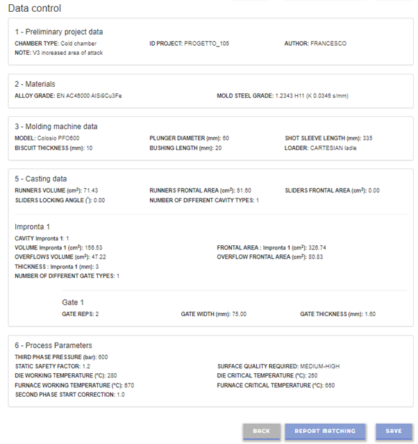
This section summarizes the data entered for further control and overall visualization. We also have the possibility to view the calculated data, the PQ2 graph and then, if necessary, to go back in the input sections to try to change some values or settings to improve the expected result of the analyzed casting.
![]()
![]()
You can view the report and the .STL files loaded at any time by accessing your personal area “My JOB” in the Matching section.
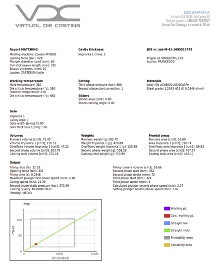
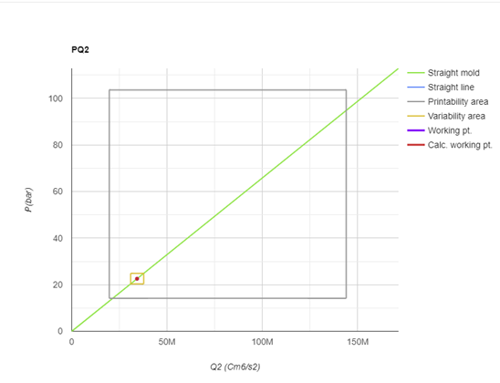
PQ2 graph. It allows a graphical visualization of the analyzed configuration. In the product chart we find:
![]()
![]()
![]() You can increase or decrease the value of the graphic scale (X/Y)
You can increase or decrease the value of the graphic scale (X/Y)
Machine line. It is the straight line that identifies the injection capacity of the molding machine. Our work area must always be below the line of the chosen machine in order to mold the considered casting. It changes as the machine, plunger and shot sleeve change.
Die line. It represents the ability of the mold to fill the cavity to guarantee the desired quality in the required time. To change the slope, the attack sections must be changed, if the gate sections are increased, the slope of the straight line increases, vice versa reducing them.
Molding rectangle. It represents the area in which we will have to stay to guarantee the production of the considered casting with the required quality. It defines a lower speed limit equal to the injection condition with spray effect, and a higher speed limit deriving from the maximum speed that can be reached on the gates (to avoid wear of the dies).
Delta rectangle. It represents the inevitable variability of the process that is observed from shot to shot due to the temperature fluctuations in the furnace, of the mold, and the plunger speed.
Calculated MACHING point. It represents the working condition expressed by the calculated speed by the software on the basis of the injection time required and the quality set.
User MATCHING point. Starting from the MATCHING configuration, we can move to the central position of the molding rectangle by acting on the user plunger speed and optimizing the machine working conditions.
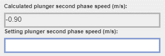
Second phase plunger speed. It is the second phase speed that the plunger must make to fill the cavities in the required time (calculated above). It is a theoretical value imagining that the entire speed is available instantly when the metal arrives at the attacks and that all of they work for the whole area available from the beginning of the second phase. You can act directly by setting a value manually that will take precedence over the calculated one.